
|
Originally Posted by bdl99 That certainly differs from the switch I was looking at, but that was in a GT-R. I have a 370z switch on order so will confirm
|
|||||||
 |
|
|
LinkBack | Thread Tools | Display Modes |
 12-10-2010, 09:57 AM
|
#91 (permalink) | |
|
A True Z Fanatic
Join Date: Dec 2009
Location: NY
Age: 38
Posts: 9,192
Drives: Z32TT & 335xi Coupe
Rep Power: 39   |

Quote:

|
|

|

|
|
12-10-2010, 10:04 AM
|
#92 (permalink) |
|
A True Z Fanatic
Join Date: Sep 2009
Location: Mod Capital of Canada
Age: 59
Posts: 7,354
Drives: cars. lots of cars.
Rep Power: 40184 |
LOL! I love this.
 I will meter out my switch again today if I get the chance. I had to buy a new meter last night as the old one crapped the bed. The reality is, we need the switch to act the way we want it too REGARDLESS of the way it behaves in the stock harness. As long as we can determine the reactions of the pins in either direction of the rocker, then all that is left to do is sort out the illumination. I am going to go for the effect of illuminating the HI and LO lights for the vss disable and camera enable, but I am going to disable the centre illumination for the heated seat emblem. Probably paint over it or cover it whatever....
__________________
 H&R / Stillen / Berk / HKS / Swift / Michelin / UpRev / SPC / Amuse Rep / Seibon / Fringe XVO / TWM / more... My Journal |
|
|
|
|
12-10-2010, 03:02 PM
|
#93 (permalink) |
|
A True Z Fanatic
Join Date: Sep 2009
Location: Mod Capital of Canada
Age: 59
Posts: 7,354
Drives: cars. lots of cars.
Rep Power: 40184 |
Lets do this the proper way.... the manual!!
Passenger side switch pins: 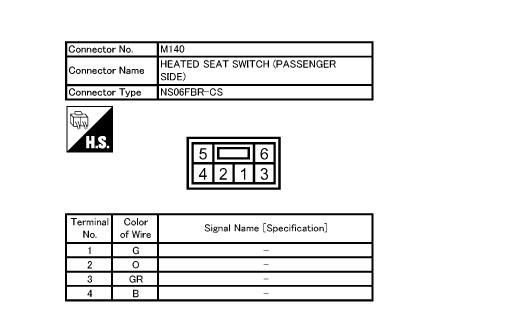 Driver side pins: 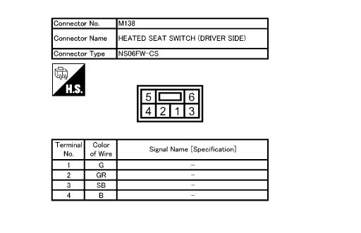 and FINALLY! The schematic for the wiring including the position of the diodes... 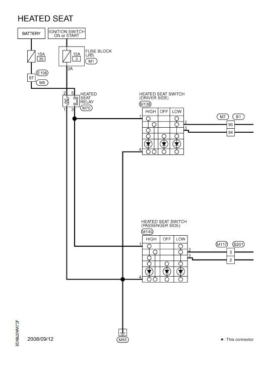 All of these images were pulled from the 2010 manual I should have gone there first...
__________________
H&R / Stillen / Berk / HKS / Swift / Michelin / UpRev / SPC / Amuse Rep / Seibon / Fringe XVO / TWM / more... My Journal |
|
|
|
|
12-10-2010, 03:03 PM
|
#94 (permalink) | |
|
A True Z Fanatic
Join Date: Jul 2010
Location: Scranton, PA
Posts: 1,580
Drives: In the fairway
Rep Power: 21 |
Quote:
 Oops, quoted an earlier post before seeing Whee!'s post above. Can you translate that (thanks for the diagram, BTW) into English for noobs like me?
__________________
 Rain, snow, sleet, hail: 2009 Mazda 3 sGT HB Everything else: 2009 370z, PW Touring 6MT Last edited by ProfessorDave; 12-10-2010 at 03:07 PM. |
|
|
|
|
|
12-10-2010, 03:09 PM
|
#95 (permalink) |
|
A True Z Fanatic
Join Date: Sep 2009
Location: Mod Capital of Canada
Age: 59
Posts: 7,354
Drives: cars. lots of cars.
Rep Power: 40184 |
New layout of pins as follows:
4 5 2 1 3 6 So I think that this is what the schematic is saying... Pin 4 is Gnd Pin 1 is 12V Pin 1 & 3 are short for the High seat temp setting (Pin 3 Hi output) Pin 1 & 2 are short for the Lo seat temp setting (Pin 2 Hi Output) Pin 5 is measured at 12V (constant supply) Pin 6 is measured at 8 V (comes on with interior lights to illuminate the seat icon) These are for the illumination circuit
__________________
H&R / Stillen / Berk / HKS / Swift / Michelin / UpRev / SPC / Amuse Rep / Seibon / Fringe XVO / TWM / more... My Journal Last edited by wheee!; 03-20-2011 at 06:13 PM. |
|
|
|
|
12-10-2010, 03:15 PM
|
#96 (permalink) |
|
A True Z Fanatic
Join Date: Jul 2010
Location: Scranton, PA
Posts: 1,580
Drives: In the fairway
Rep Power: 21 |
 Awesome, thanks! This stuff makes my head hurt. My brain doesn't work this way. I can wire up a 3-way switch in my house, but I get into the car and 
__________________
Rain, snow, sleet, hail: 2009 Mazda 3 sGT HB Everything else: 2009 370z, PW Touring 6MT |
|
|
|
|
12-10-2010, 03:41 PM
|
#97 (permalink) | |
|
Base Member
Join Date: Oct 2010
Location: NJ
Posts: 244
Drives: Nissan GT-R 2011
Rep Power: 16 |
Quote:
 The only difference is the diagram is from the harness perspective and mine was from the switch 1 2 3 4 5 6 Mine looking at switch 4 5 2 1 3 6 Diagram from manual looking at harness 1 (3) 2 (6) 3 (1) 4 (2) 5 (4) 6 (5) Showing both (harness in brackets) The reason for the metering voltages between (5) and (6) is due to metering before and after the bulb. |
|
|
|
|
|
12-10-2010, 03:43 PM
|
#98 (permalink) |
|
A True Z Fanatic
Join Date: Sep 2009
Location: Mod Capital of Canada
Age: 59
Posts: 7,354
Drives: cars. lots of cars.
Rep Power: 40184 |
This is actually awesome news as now we can wire the hi output (HI setting) from pin 3 to the relay to release the vss signal, and when we switch to the LO setting it will send a 12v signal from pin 2 directly to the reverse signal on pin 81 at the back of the av head. No extra diodes should be required.
What say you Brian?
__________________
H&R / Stillen / Berk / HKS / Swift / Michelin / UpRev / SPC / Amuse Rep / Seibon / Fringe XVO / TWM / more... My Journal |
|
|
|
|
12-10-2010, 03:58 PM
|
#99 (permalink) | |
|
Base Member
Join Date: Oct 2010
Location: NJ
Posts: 244
Drives: Nissan GT-R 2011
Rep Power: 16 |
Quote:
Regarding the diodes you still want at least one diode so that the 12V doesn't back feed the car when the switch is engaged (remember we are tapping in to the existing wire not cutting it). Given that the diodes cost cents I would probably also include the second so that when you put the car in reverse it didn't illuminate the button. I would need to double check the rest of the circuit diagram to see if that would actually happen but a diode would solve the problem either way. |
|
|
|
|
|
12-10-2010, 04:00 PM
|
#100 (permalink) | |
|
A True Z Fanatic
Join Date: Sep 2009
Location: Mod Capital of Canada
Age: 59
Posts: 7,354
Drives: cars. lots of cars.
Rep Power: 40184 |
Quote:
Pin 4 is top left on the switch, top right on the harness. It is a black wire (indicating ground I assume) and next to it is pin 5 (red wire) which is 12v constant. As for 5 & 6, are you saying that that is strictly for the centre "seat" icon to light up? That would make sense too if the LED's for the heat indicators are pulling their voltage from pin 1 (12v) Sorry if this is becoming semantic at all, just trying to be as clear as possible!
__________________
H&R / Stillen / Berk / HKS / Swift / Michelin / UpRev / SPC / Amuse Rep / Seibon / Fringe XVO / TWM / more... My Journal |
|
|
|
|
|
12-10-2010, 04:12 PM
|
#101 (permalink) |
|
A True Z Fanatic
Join Date: Sep 2009
Location: Mod Capital of Canada
Age: 59
Posts: 7,354
Drives: cars. lots of cars.
Rep Power: 40184 |
Actually I agree with you on the diodes. Looking at the schematic it would still need protection from turning the switch lights on when you went into reverse etc. Good call!
__________________
H&R / Stillen / Berk / HKS / Swift / Michelin / UpRev / SPC / Amuse Rep / Seibon / Fringe XVO / TWM / more... My Journal |
|
|
|
|
12-10-2010, 04:59 PM
|
#102 (permalink) | |||
|
Base Member
Join Date: Oct 2010
Location: NJ
Posts: 244
Drives: Nissan GT-R 2011
Rep Power: 16 |
Quote:
Quote:
Quote:
for anyone taking the complete DIY approach it will probably need a photo or two 
|
|||
|
|
|
|
12-10-2010, 05:16 PM
|
#103 (permalink) |
|
A True Z Fanatic
Join Date: Sep 2009
Location: Mod Capital of Canada
Age: 59
Posts: 7,354
Drives: cars. lots of cars.
Rep Power: 40184 |
I will never doubt you again.. I have been
 
__________________
H&R / Stillen / Berk / HKS / Swift / Michelin / UpRev / SPC / Amuse Rep / Seibon / Fringe XVO / TWM / more... My Journal |
|
|
|
|
| Bookmarks |
| Thread Tools | |
| Display Modes | |
|
|
 Similar Threads
|
||||
| Thread | Thread Starter | Forum | Replies | Last Post |
| Backup Camera on 370Z | sbkim | Audio & Video | 41 | 01-18-2023 07:29 PM |
| Backup Camera in 2010 with Nav | axeman71 | Audio & Video | 1 | 04-07-2013 02:09 PM |
| Backup camera and Reverse light | Trolling222 | Audio & Video | 8 | 05-10-2010 11:31 AM |
| OEM Backup camera for stock NAV! | z370z | Canada | 2 | 02-05-2010 08:07 AM |
| Has anyone installed a backup camera w/stock nav? | trema | Audio & Video | 10 | 03-03-2009 02:39 PM |


 3Likes

 This is more interesting than taking a class


 Linear Mode


