
|
Looks like 09/10 Max's are having that problem as well. Will not start - Maxima Forums
|
|||||||
 |
|
|
LinkBack | Thread Tools | Display Modes |
 01-17-2012, 03:02 PM
|
#47 (permalink) |
|
A True Z Fanatic
 Join Date: Aug 2009
Location: N/A
Posts: 76,801
Drives: N/A
Rep Power: 141523   |

based on info at courtesyparts the 09+ maxima's are using a slightly different lock... but might be the same issue.
Product SKU: 48700-A35001 Ours is: 48700-JF00A (revB, C, D) |

|

|
|
01-17-2012, 03:04 PM
|
#48 (permalink) |
|
A True Z Fanatic
 
Join Date: Mar 2009
Location: Houston, TX
Posts: 4,024
Drives: too slow
Rep Power: 3596 |
I haven't been able to find this in the Service Manual (censored so as not to aid theft?), but what would happen if you just removed the whole thing from the steering column and never re-installed it? Just never locks up? Not a huge issue IMHO. Would the car throw a code with it unplugged? I wonder if it's one UpRev can silence.
|
|
|
|
|
01-17-2012, 03:11 PM
|
#49 (permalink) | |
|
A True Z Fanatic
Join Date: Aug 2009
Location: N/A
Posts: 76,801
Drives: N/A
Rep Power: 141523 |
Quote:
|
|
|
|
|
|
01-17-2012, 03:13 PM
|
#50 (permalink) | |
|
Track Member

Join Date: Sep 2009
Location: Manhattan Beach, Ca
Posts: 604
Drives: 16 LEX GS,09 Z,03Max
Rep Power: 19 |
Quote:
|
|
|
|
|
|
01-18-2012, 07:53 AM
|
#51 (permalink) |
|
Base Member
Join Date: Aug 2010
Location: Andorre
Posts: 90
Drives: 2010 370Z M6
Rep Power: 18 |
Mine was intermittent (a bit like a manual lock needing a shake and seemed normal enough) but then expired...... and is on hold for possible warranty, if winter wheels and tires do not void it. Tricky Niss.
"Must be manufactured" in 2010 was my written deal on the car itself. The type B steering lock was made in early 2009 and the gas pedal assy made in late 2008. Is that normal on a 2010 build car? What happened to Just-in-time (JIT) production methods...I wonder. Apart from un- reliability---4+ times now--the car's great. A curate's egg. Any folk with an old lock? I'd like to disect it and try a relay to fool the CPU/BCM into thinking the lock is there. A real ignition switch and starter button could be nice too. How are steering lock messages sent to the electronics to allow the engine to start ? Fritz |
|
|
|
|
01-18-2012, 08:47 AM
|
#52 (permalink) |
|
A True Z Fanatic
Join Date: Mar 2009
Location: Houston, TX
Posts: 4,024
Drives: too slow
Rep Power: 3596 |
EDIT: Scratch that idea, there's no easy way to fake it with a relay. Most of it is trivially fake-able since it's just "apply voltage to energize" and 2x redundant inverted feedback status switches that inform BCM + IPDM E/R whether the lock is in the commanded state, but then there's one critical bit that wouldn't work out: the BCM feedback on pin 111, which actually expects some timed pulses and state changes from some controller inside the lock unit in response to lock/unlock commands. So you'd need something a little more complex to fake it, like a cheap little microcontroller.
Even if you replaced the lock unit with a microcontroller-based fake: if you ever turned the steering wheel while the BCM thought it was locked, I wouldn't be surprised if it a threw a code because the steering angle changed when it shouldn't be possible. Last edited by wstar; 01-18-2012 at 09:14 AM. |
|
|
|
|
01-18-2012, 09:20 AM
|
#54 (permalink) | |
|
A True Z Fanatic

Join Date: Mar 2009
Location: North East
Posts: 6,203
Drives: 09 370Z Sport M6
Rep Power: 655 |
Quote:
__________________
Hotchkis ARB | Stillen CAI | Art Pipes | Berk CBE | Stillen AP Racing Brakes | AE Performance Oil Cooler | BC Racing ER Coilovers | Doran Control Arms |
|
|
|
|
|
01-18-2012, 11:56 AM
|
#56 (permalink) | |
|
A True Z Fanatic
Join Date: Mar 2009
Location: North East
Posts: 6,203
Drives: 09 370Z Sport M6
Rep Power: 655 |
Quote:
__________________
Hotchkis ARB | Stillen CAI | Art Pipes | Berk CBE | Stillen AP Racing Brakes | AE Performance Oil Cooler | BC Racing ER Coilovers | Doran Control Arms |
|
|
|
|
|
01-18-2012, 12:03 PM
|
#57 (permalink) |
|
A True Z Fanatic
Join Date: Mar 2009
Location: Houston, TX
Posts: 4,024
Drives: too slow
Rep Power: 3596 |
Hmm I still think I don't quite understand it. I blame Nissan's documentation
 This is my best current guess at how the whole thing operates, now: This is my best current guess at how the whole thing operates, now:The lock unit supposedly has 7 pins on it. I'm giving them my own names for now since I still haven't found a pinout for connector M40, which is the actual connector at the lock unit: G1: Grounded permanently G2: Grounded permanently P1: power supply, switched by IPDM E/R P2: power supply, switched by BCM S1: feedback switch output: +12V when locked, 0V when unlocked S2: feedback switch output: 0V when locked, +12V when unlocked C: communication line between lock module and BCM Physical states: The steering lock can be in one of two physical states: locked or unlocked. Once it has switched to a given state, it will remain in that state until commanded to change, regardless of whether any power is supplied to the unit. No relay has to remain energized to maintain one of the states or anything like that. Power supply states: P1 (IPDM E/R): When ignition is ACC or ON, no voltage supplied. Temporarily supplies battery voltage for a short while after opening the driver's door when ignition is OFF, or after pushing the ignition button once when it's LOCKed. P2 (BCM): When ignition is OFF or ACC, +12V is supplied. When ignition is ON, it is not. None of this completely makes sense, but the bottom line is, when the ignition is ON, neither power supply pin gets voltage, so no change to steering lock status can occur. When ignition is not ON, one of the two power pins (or both) will give it power at the right times for it to respond to a lock or unlock command, somehow. It could be the case that P1 (IPDM E/R) only powers the feedback switches that drive S1 and S2, and P2 (BCM) powers everything else (the mini-controller that communicates with the BCM and actually moves the lock) Switch states: The S1 and S2 outputs are redundant inverted status outputs. They're almost certainly driven by physical switches that are tripped by the locking mechanism itself. In the unlocked state only one of them provides +12V, and in the locked state only the other does. If they're both +12V or both not +12V, that triggers a diagnostic failure. If they don't feedback that commands were followed correctly, that also triggers a diagnostic failure. Also of note: these are connected to both the IPDM E/R and the BCM, so for some reason both modules want to see this status. BCM Communication Line: This is the perplexing 7th pin "C": 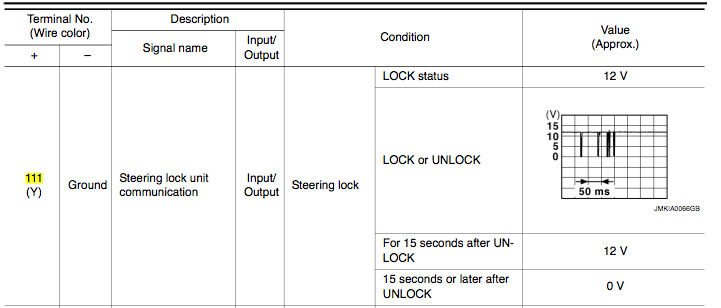 It's listed as both an input and an output for the BCM. It seems definitely sure that the BCM is who sends that little pulse train against a 12V background to send LOCK and UNLOCK commands, as an output. I misunderstood earlier that the pulse train came from the lock module. What really makes no sense is how any of this could be an input back to the BCM. Maybe it's mislabeled (from my point of view), and it's a BCM-output only, and the BCM drives it at +12V while LOCKED, and 0V when unlocked for 15+ seconds, and whenever it wants to send a command, it applies the +12V (if unlocked before) and then sends the pulse signal. I guess someone would have to figure out what the manual means by clipping onto this with a scope (or really, even a multi-meter would do, since the only complex bit is already documented in the diagram above). Last edited by wstar; 01-18-2012 at 12:21 PM. |
|
|
|
|
01-18-2012, 12:25 PM
|
#58 (permalink) | |
|
A True Z Fanatic
Join Date: Mar 2009
Location: North East
Posts: 6,203
Drives: 09 370Z Sport M6
Rep Power: 655 |
Quote:
I think the main thing it going to be giving the ECU the correct signals on 97 (S1), 98 (S2).
__________________
Hotchkis ARB | Stillen CAI | Art Pipes | Berk CBE | Stillen AP Racing Brakes | AE Performance Oil Cooler | BC Racing ER Coilovers | Doran Control Arms |
|
|
|
|
|
01-18-2012, 12:34 PM
|
#59 (permalink) | |
|
A True Z Fanatic
Join Date: Mar 2009
Location: Houston, TX
Posts: 4,024
Drives: too slow
Rep Power: 3596 |
Quote:
What I don't understand is whether the lock module also supplies voltage to this wire at times to provide feedback to the BCM or something. One way or another, a replacement would need: a cheap microcontroller to sense the command pulses on the communication line and update a little NVRAM state indicating whether the fake lock is currently stuck-on or stuck-off, the microcontroller would need to be powered on any time either of the power supply pins lights up and provide S1/S2 feedback based on NVRAM, and possibly voltage feedback on the communication line as well. |
|
|
|
|
|
01-18-2012, 12:36 PM
|
#60 (permalink) |
|
A True Z Fanatic
Join Date: Mar 2009
Location: Houston, TX
Posts: 4,024
Drives: too slow
Rep Power: 3596 |
Of course, for a race car you could probably remove this module completely and it would be ignored as part of disabling all anti-theft code via UpRev. Mostly I'm just thinking about whether we could make a cheap small replacement to avoid $500 when an A/B-series unit fails, or to swap in preemptively and avoid failure.
|
|
|
|
|
| Bookmarks |
|
|
 Similar Threads
|
||||
| Thread | Thread Starter | Forum | Replies | Last Post |
| Just joined the "Dreaded Steering Lock Club" | Timotay | New Forum Member | 2 | 03-06-2013 04:40 PM |
| Need a steering lock assembly!! | bfowlzr33 | Wanted | 8 | 01-02-2013 04:40 PM |
| Dreaded steering lock | Jim Roberts | Exterior & Interior | 2 | 12-12-2012 03:08 PM |
| Steering lock repair | fritz | DIY Section (Do-It-Yourself) | 38 | 02-22-2012 09:30 PM |


 61Likes



 Linear Mode


