
|
Gday Z fam, I received my 21 Nismo in April last year (in Australia), I chose the Z over any other brand new cars that were available since there is
|
|||||||
 |
|
|
LinkBack | Thread Tools | Display Modes |
 01-06-2022, 04:03 AM
|
#1 (permalink) |
|
Base Member
Join Date: Aug 2021
Location: Brisbane Australia
Posts: 1
Drives: 21 Nismo silver MT
Rep Power: 3368   |
Gday Z fam,
I received my 21 Nismo in April last year (in Australia), I chose the Z over any other brand new cars that were available since there is little to no electronics assisting you drive the car, they are still (IMO) a true drives car with minimal interference which I enjoy. So with that in mind once I got her I immediately wanted to be able to remove all the nannies that the 370 still has, yaw control and the throttle cut when you are left foot braking/doing a burnout, etc. I spent quite a while looking into how different people had gone about it and while the videos and forum DIYs I found was helpful, I thought that there was room for improvement. So hopefully I can help people with what I would consider the correct way to do this. So here is my (first ever) how to thread and walkthrough on what I did to remove the nannies from my Nismo. It is a good idea to read through the whole thing before starting as there is info throughout that you may need to know before starting.  This should go without saying but follow this at your own risk and ensure you are comfortable and capable of carrying out the job before starting it. If you do so it is at your own risk. But this is fairly simple IMO and quite fun if you are just dabbling in mods for your Z  Alright so the whole idea of this is to remove the nannies, but for anyone that this is the first place the have looked: even when you hit the traction control switch on the dash, it doesnt fully cut everything. There are still two occasions when the ecu will interfere: - If it senses the car get sideways (via the yaw sensor) then traction control will kick in. For this we kill power to the yaw sensor. - If you have you foot on the accelerator and the brake at the same time (like you are doing a standing burnout, wanting to maintain proximity in a drift, brake boost, etc) it will cut the throttle as this is a safety feature. For this we interrupt the signal to the ECU. (As it turns out however, this no longer works for the 2016+ Zs, much to my chagrin. However I have still included what I did for everyone that is pre 2016) You dont have to do both, you can do either. You can also just unplug the yaw sensor if you want, you will get the slip indicator light on the dash but it wont log any fault codes. But to interrupt the brake signal to the ecu, you need a switch as if it doesnt sense it for an extended period it will log a fault code. If you have ECUTEK I believe there are ways to disable them in there but I have no experience with that yet. With the theory out of the way, lets dive in. Tooling that I used: - Small flat head screw driver - Various torches/lighting (I used a Milwaukee bonnet light and a few magnetic LED lights) - Stanley knife/razor blade - Side Cutters - Crimping tools (you can go as crazy as you want with these but a good value option are these ( https://www.ebay.com.au/itm/S-G-TOOL...-127632-2357-0 you can search the part number listed to find them elsewhere) - Heat gun with a shield -Multimeter and leads  Consumables: - Tesa Tape (this is the cloth tape most modern OE manufacturers use these days. Tesa is the brand, you dont need genuine Tesa but there are a lot of cheaper ones that are cancer to use so be aware of that when buying) - Open barrel crimps (there are multiple types and styles of crimps, all have their own specific use and pros and cons. Open barrel crimps are cheap, easy to use and can be used in a variety of ways which makes them good value and why I use them for most automotive wiring and why I have chosen them here. Your pre insulated repco specials are IMO bulky, primitive and tend to damage all the wires around them over time) - Heat shrink in various sizes (I used Raychem as I had, but you can reply use any, keeping in mind the quality of the heat shrink you are using. Having dual wall heat shrink with a sealant inside is handy in some cases here) - Wire (again quality is the biggest thing here, I used M27500-22 twisted pair for the brake switch as I had it, but thats pretty extra for a job like this. TXL or cannibalising a some wire off a factory wiring loom would be the minimum I would use. PVC insulated wire (like Narva wire we have here in Australia) may be cheap but is if very low quality and more often then not you melt the PVC before you shrink any heat shrink you use) - 2x Switches (I wanted something that looked as OEM as possible, so I got some Nissan sized push bottom switches from Lightforce, you can choose from a range of symbols and writing to put on it and its a direct fitment for the centre console switch blanks) ( https://au.lightforce.com/collection...-suit-nissan-1 ) Tesa Tape  A variety of splices. Open barrel are the U shaped ones.  Heat shrink I used  The switches   Alright, as with any time you are playing with electronics: disconnect your battery and ensure the terminal cannot fall back onto the battery and accidentally recomplete the circuit. (keep in mind that the windows will now NOT partially open to allow the door to open, so have them in the partial open position or fully open before disconnecting the battery) You can pull the cup holder out by putting your hand into the holder and pulling up gently, you shouldnt need to yank you out to much force into it, but it does require a bit of a tug. Disconnect the plugs and loom clips so you can fully remove the cup holder piece. From here it depends wether you are doing the yaw sensor or the brake signal switch so go to the appropriate instruction to suit your needs. Follow this part for the Yaw Sensor Switch: From here you will be able to see a factory loom under the centre console. The main loom is (on mine) a blueish colour and there are two small lengths coming off that have a corrugated case and black tape over them. There will be 1-2cm of exposed wires where these smaller looms join the main loom, look for the green wire in this portion, that is the power wire for the Yaw sensor and that is what we are switching.  Using the knife (VERY CAREFULLY) cut back some of the grey/blue insulation on the main harness to give more access to the wires we are looking at. Go slowly to make sure you dont cut the wires underneath! I cut about 3-4cm from where the wires go into the loom, forward towards the front of the car and this gave me lots of access. Isolate the green wire as shown.  Cut the green wire in the middle and trim back the insulation on both sides of the wire, being careful not to damage the conductor underneath. Cut enough back so you have about a finger nails width either side of the crimp you are using. I like to use a sharp knife here and roll the wire over the blade with a finger, you dont need to put much pressure on the wire, let the blade do the work. There is a chance of cutting yourself but if you put enough pressure on to cut yourself then you are putting on too much pressure anyway. But still, be careful!  Now the next part depends on what switches you are choosing to use so there is a variety of ways you can go about it. The lightforce switches I have, come with a plug and fly loom which makes their very neat and tidy! I will show you the way I did it because of the switch I have and then cover a few other options at the end. Being that my switches have a plug and fly lead with 4x wires, i followed the manufacturers instructions to see what wire colours did what. Blue and yellow were for either side of the switch, so one would need to be attached to either side of the cut green wire. It is just a switch so polarity is not important here. It is however important at this point to ensure that you have enough length in your wires to enable you to plug the wires, once attached to the car, into the switch and cup holder, so double check this and trim or add wire to suit. To make looming neater and easier later on, I chose to but splice one of the line and end to end splice the other, this means that the new wires that are being added will both be going in the same direction and can lay neatly once loomed and lake up the minimum amount of room. Once this is done you can loom it all up with the Tesa tape to keep it tidy.      If your switch does not have a fly lead like mine and has solder terminals or spade terminals on the bottom then you can do the same as above, however you will also need to add the appropriate termination to the other end of the new wires you have just added. If the switch has spade terminals than you will simply need to crimp a female terminal onto the new wires so you can connect to the switch, ensuring that the terminals are insulated so in the event they get disconnected, they cant arc out against each other and blow a fuse or worse. If you have solder terminals on your switch this is more challenging as you will need to put a plug somewhere so you can actually disconnect it. I personally would just go get a switch that doesnt need to be soldered but if that is all you have, then add a 2 pin DTM Deutsch plug or similar in between the switch and the car wiring, on the new wires you have just added. But make sure you add enough length to the wires that the plug and be stashed in one of the homes so it doesnt get in the way of the cup holder being refitted. Also ensure you strain relieve the crimp and best you can with a potting compound or similar to ensure they wouldnt break and car arc if the do break. And that completes the Yaw sensor switch. If you arent doing the brake sensor than skip to the end for any follow on that is required. Brake signal switch (remember that this DOES NOT work for 2016+ models): From here there are a few options: you can splice at the ECU or at the fuse box. I chose to splice in at the fuse box in the drivers (RHS for me) kick panel as this gave the most access. See the diagrams below.   Now you will want to run two wires (or a twisted pair like I did) from the switch to the fuse box. Try and keep it as tucked out of the way as you can do it is neat and wont fall in front of your feet. You will need to remove the drivers (RHS) door trim and then remove the kick panel to access the use box, they both just pull out of their clips with a little encouragement. At the fuse box is very similar to cutting and splice the yaw sensor. However, in Nissans infinite wisdom they decided that wire colours are a waste of time and to put what ever colour they wanted where ever they wanted and mine is yellow, not pink as the FSM would indicate thanks Nissan for that. So make sure you get the correct wire. It is the centre plug in the fuse box as you see in the photos. Pull that out and find 3B as shown in the diagram. It is the wire directly next to the plug release clip. We are going to want to cut that wire (mine being yellow, your may not be), and splice out two wires that have been run to the switch, to either side of the cut wires. Similar to the yaw sensor I did an end to end splice on the wire coming out of the plug and I did a butt splice on the wire going into the loom. This allows for the wires to then run next to each other smoothly and makes it cleaner and less bulky. Once done, plug the connector back in and loom it up with some Tesa tape nicely.     Now for the switch again the next part is pretty much exactly the same as before and part depends on what switches you are choosing to use so there is a variety of ways you can go about it. The lightforce switches I have, come with a plug and fly loom which makes their very neat and tidy! I will show you the way I did it because of the switch I have and then cover a few other options at the end. Being that my switches have a plug and fly lead with 4x wires, i followed the manufacturers instructions to see what wire colours did what. Blue and yellow were for either side of the switch, so one would need to be attached to each of the two wires you have run to the fuse box. It is just a switch so polarity is not important here. It is however important at this point to ensure that you have enough length in your wires to enable you to plug the wires, once attached to the car, into the switch and cup holder, so double check this and trim or add wire to suit. On this switch I did both as an end to end splice since they would be loomed in line, make sure you put the head shrink on before splicing the wires together.  Follow On: From here, you switch may need its own switched 12V and ground if it has LEDs in it. Having a Nismo, I only have the boot open switch, I do not have the two heated seat switches. Either way there will be a plug in there that is for whichever switch you do not have (heated seat switch or boot switch). I got the ground and headlight switched 12V for the switches illumination from this plug. Since I was doing both the yaw and brake switches I spliced the 12V for both and the ground for both together so they could use the same source. To limit the amount of impact on the factory wiring, I chose to pull 2x male pins out of a R33 loom I have laying around to plug into the factory plug and therefore not need any cutting or crimping. If you dont have this option you can simply strip a section of insulation back (again the size of your crimp, plus a nail width at either side) and crimp your new wires to the now exposed conductor. To find what wires are the ground and switch 12V source for the illumination you will need your Multimeter. The switched 12V will have no power until you have the lights switched on, then it will have 12V. Where the ground will be a constant open circuit to a piece of metal on the chassis (I used the handbrake adjuster from memory). For me; When looking at the plug with the locking tab away from you, the two pins were the far RH pins, and we black and black with the red stripe (colours may vary on your car so double check with a multimeter!!). As you can see in the photos; I butt spliced the two 12V wires from the switches and the wire and pin I am using to plug into the factory connector together. Then I did the same for the grounds. I heat shrunk both separately to insulate the crimp, then both together to stabilise them. Then I used the Tesa tape to hold them all in place so they could not come out. Although this is far from ideal, having the correct female connector would be the best way of doing this, this method is quite secure and unlikely to cause issues and works perfectly. Again I only did this to limit the amount of cutting I was doing to the factory loom, if you dont mind doing more cutting then feel free to follow the other method and use an inline splice like the last photo here. To insulate it, you can swoon the connector and slide heat shrink over it, or use Tesa tape to cover the splices.     If you are happy to splice into the factory harness for the 12v and ground simply strip back a section of the insulation as you see below and place the open barrel splice around the exposed portion of the wire you are splicing too and the wire you are adding, then crimp down. As previously stated, depinning The connector will allow you to heat shrink it, or wrap with Tesa tape.  From here final looming of all the wires is needed to make sure it is all neat and tidy. Use Tesa tape as required to loom u der the cup holder keeping in mind where the wrong needs to sit once the cup holder is put back in place. This is how mine looked.  Now the switches I chose are push button switches. This means they are closed when they are depressed. So for it to be in factory position and the nannies active the need to be in the down position or on. Turning them off or the up position will kill the nannies. This is a little triggering for my OCD but thats just the nature of the switches that are available. When they are off, you will get the ABS and slip warning lights on the dash and you will need to depress the switches and then cycle power in order to turn them back on again. Remembering that killing the brake switch for a period of time will latch a code in the ECU. Now addressing the controversy of crimp Vs solder. I have obviously chosen the crimp method as in my opinion (I want to stress that its my opinion, you are welcome to your own) it is the better option. You can use solder if you wish in your car, but in any form of professional Motorsport or aeronautical wiring (where most Motorsport wiring rules originally came from), solder is only used in very specific and limited circumstances. This is my background and this is why I have chosen and encourage this method over solder. If you need information on wiring methods I have used or want to learn more; High Performance Academy has a wiring course and has multiple videos on the subject as well as their own forum with a wealth of knowledge available. I have no affiliation to them but find them a very valuable resource for ALOT of car related information. I hope I have helped and not confused people with this. Please recommend anything I have missed, let me know anything that is confusing so hopefully I can make it easier as we go. Happy skidding |

|

|
|
07-24-2022, 06:18 AM
|
#2 (permalink) |
|
Track Member
Join Date: May 2021
Location: slovenia
Posts: 605
Drives: 370z pack
Rep Power: 125429 |
Nice tutorial, I especially like the switches and markings, they look PERFECT.
I already did the drift switch quite a while ago, but I'm looking into doing a burnout switch now. I was thinking of doing it via the connector behind the glove compartment, but I think I'll follow your way. Thanks for the tips! |
|
|
|
|
07-27-2022, 01:48 PM
|
#3 (permalink) |
|
Base Member
Join Date: Apr 2021
Location: Florida
Posts: 216
Drives: G37S
Rep Power: 26850 |
My attempt at it was to purchase new YAW connectors to avoid cutting. Worked great however after finding the 2016+ issue with brake override decided to stop making them.
The connectors are not that expensive and it exercises the need to make a harness which is always a great excuse for me. Great job on the switches. Here's mine. 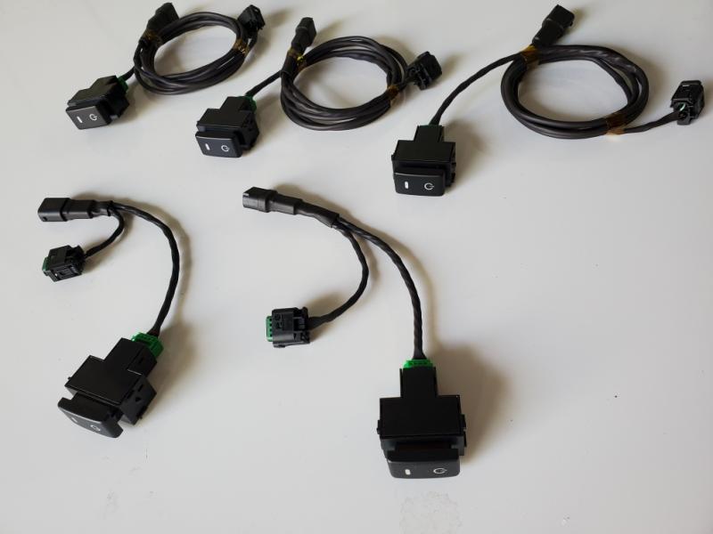
|
|
|
|
|
08-16-2023, 02:00 AM
|
#5 (permalink) |
|
Base Member
Join Date: Mar 2018
Location: Des Moines, Iowa
Posts: 181
Drives: 2014 370z Nismo
Rep Power: 7053 |
Are you selling these switches?
__________________
2014 370z Nismo Fairlady | Gold Powdercoated Nismo Rays | Z1 Ported Manifold | RJM Adjustable Clutch Pedal | Berk Test Pipes | Beluga Racing Exhaust | Custom Billetworkz Imperial Sledge Shift Knob | Carbon Fiber, Flat-Bottom Steering Wheel | Ecu-Tek Custom Tune
|
|
|
|
|
| Bookmarks |
|
|
 Similar Threads
|
||||
| Thread | Thread Starter | Forum | Replies | Last Post |
| DIY Yaw Sensor rocker switch | dP3NGU1N | DIY Section (Do-It-Yourself) | 73 | 08-28-2023 09:08 PM |
| Yaw sensor switch | dimitarm | Exterior & Interior | 33 | 08-09-2017 10:13 PM |
| Let's see your YAW sensor switch | ufoz8mycow | Exterior & Interior | 2 | 07-17-2017 08:38 PM |
| Help PLEASE! - Yaw Sensor Switch Major issue | sschaffer27 | DIY Section (Do-It-Yourself) | 13 | 05-31-2016 06:44 AM |
| YAW Sensor Rocker Switch | dP3NGU1N | DIY Section (Do-It-Yourself) | 23 | 11-10-2013 05:57 PM |


 19Likes


 Linear Mode


