I decided to try and fabricate these cooling ducts after experiencing and debating about the dreaded "ice mode". There is a lot of debate what causes this and I am not proposing that getting air to the brakes will absolutely cure the problem.
However, in my case the brake ducts worked. I am by no means an advanced level driver, but I regularly do track days at Summit Point Race Way. Before installing the brake ducts I experienced "ice mode" on multiple occasions. After installing these brake ducts I did not experience "ice mode" once. Although, I did upgrade my pads to Carbo Tech XP10/F and XP8/R and use Castrol SRF brake fluid as well.
The June 2010 Car and Driver article on what caused the Nismo brake failure made me take a second look at how air flow is directed in our cars. With all the radiator baffling and deep wheel wells there really is no where clean air can reach the wheel wells. These ducts change all that.
To begin with please refer to
http://www.the370z.com/diy-section-d...ur-airbox.html
You will need about 11 feet of 2.5 inch brake tubing, a whole bunch of zip ties, and only two aluminum flanges (because you are no longer installing the flanges on the air boxes. FYI-My brake ducts actually started as ModShack forced air intakes.
To begin, follow ModShack’s instructions to remove the nose and backing plates. Then install the fang vent flanges as per his instructions.
Now is when things get different. Remove the plastic baffling on the left and right side of the radiator. This requires removing two screws for each side on the under cover and a couple of the snap inserts.
Here is a preview.
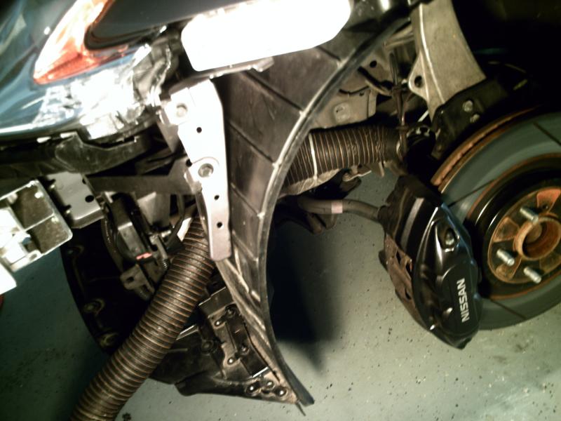
Then from the driver side wheel well remove two small plastic covers that have the words 2WD molded into them. Now you get a look at how much room is available to route the brake tubing. Not much!
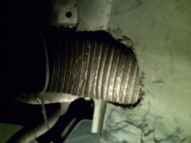
Now take a deep breath and get your dremel tool. You will need to cut a passage through the wheel well for the brake tubing. My cuts are a little crude but do the job. Keep in mind that the wheel well becomes the support bracket for the tubing. Later, you will also be flattening the tubing a little to allow for tire clearance.
I suggest using as long of section of brake tubing as you can for each side. If you have a 11 foot section (this seems to be the normal size) cut it directly in half.
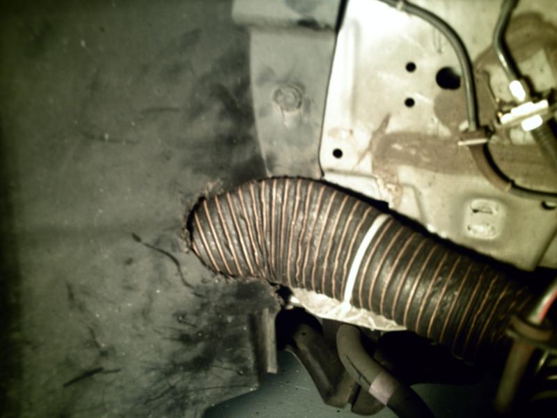
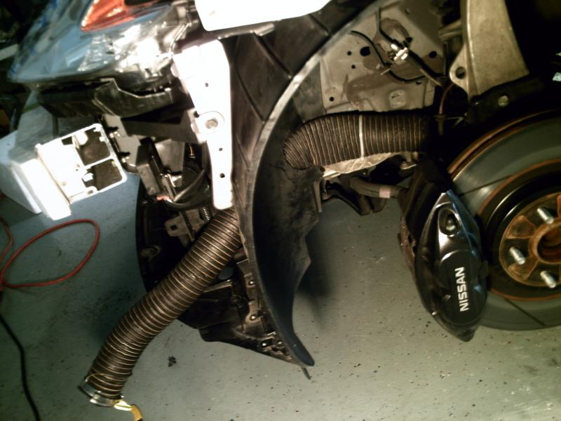
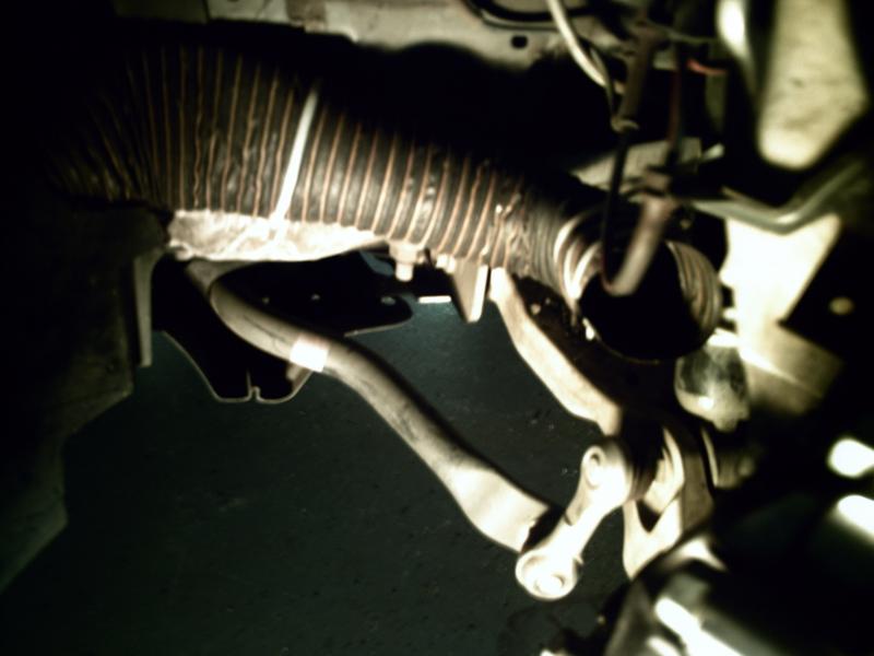
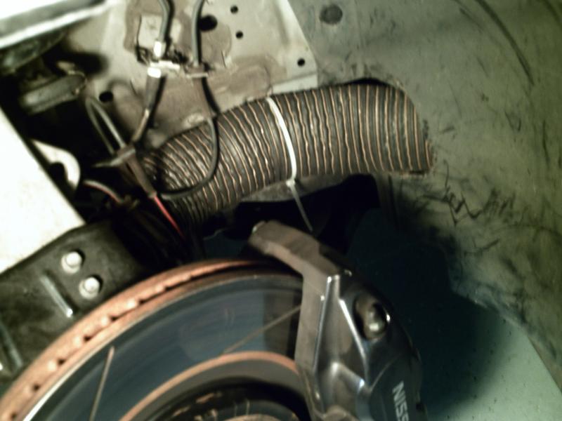
After you re-attach the wheel well cover the tubing will be held in very firmly in place. Take the end of the tube and lightly zip tie it to the front side of the shock absorber. This forces the tubing to make an abrupt 90 degree angle pointing toward the rotor.
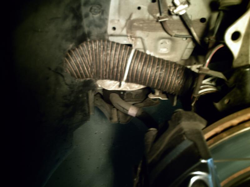
By this point you will see that the design of our front spindle really makes direct access the inside of the rotor difficult. Hopefully, someone will take this a step further and connect the tubing to a spindle duct. However, I can confirm that just getting air into the wheel dramatically helps.
A added benefit to connecting the tubing to the shock is that the tubing does not deflect when you turn your wheels.
You can play around with how much you want the tubing to extend past the shock absorber. Remember, I had already cut my tubing to be a forced air duct and was limited accordingly.
When everything looks good, go to town with the zip ties. Then get them good and tight. I probably over did it, but better safe then sorry.
Now, install your driver side wheel and check for clearance. You will probably have to compress the brake tubing somewhat. I found that my foot worked perfectly. Keep in mind that I have good clearance even with 265's up front.
Some more pics...

Now for the passenger side.
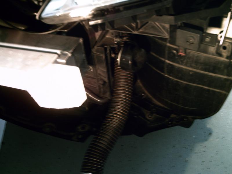
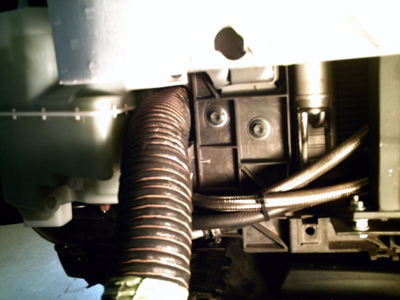
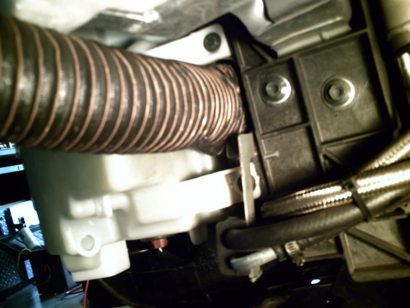
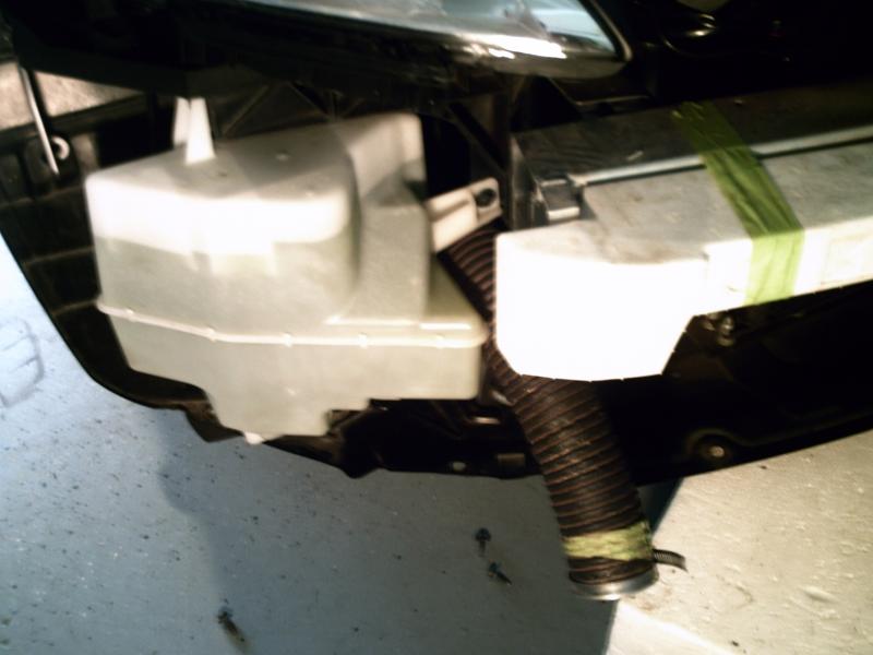
This requires cutting of the coolant container bracket to make a passage just barely wide enough to route the 2.5 inch tubing. To be honest, you would have to make some major alterations if you were to use tubing any bigger.
I forgot to take a before picture so you will have to use your imagination. Just cut out all the material where you see my tubing routed. And be careful not to cut into the coolant container!

Now repeat wht you did on the driver side and cut the wheel well and route the tubing.
Again check for wheel clearance and go to town with the zip ties.
With everything installed take another deep breath and begin the process of installing the nose and hooking up the fang vents.
Hopefully, you have plenty of tubing to connect to the fang ducts but it is tricky and deceiving. Too much and the tubing binds and you cannot install the nose or too little and it just wont fit or it tears off your fang vent. Be patient and take your time.
Once you have connected the tubing to the fang vents try and install the nose. I suggest having a couple snap clips on hand to hold the nose in place. If everything went as to plan, the side clips on the nose should hook in and hold the nose. If it just won’t fit, check your hose length and determine if it is too short or long.
Now insert the screws connecting the nose to the under tray. Things may be tight and require some coaxing.
The same goes for the wheel wells. Things will be tight.
Now get to the track and let me know if it helped!
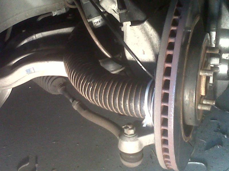
Here is how you can route the hose directly to the rotor:
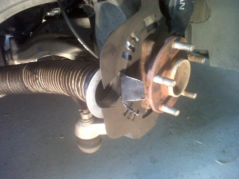
First I positioned the aluminum duct on the dust shield and used a sharpie marker to outline the inside of the duct. Next I used some sheet metal shears to cut the dust shield.
Make sure you wear heavy gloves to avoid cutting your hands!


Then I drilled a hole through the dust shield and duct. I used three pop rivets to attach the duct.
***IMPORTANT NOTE!!!
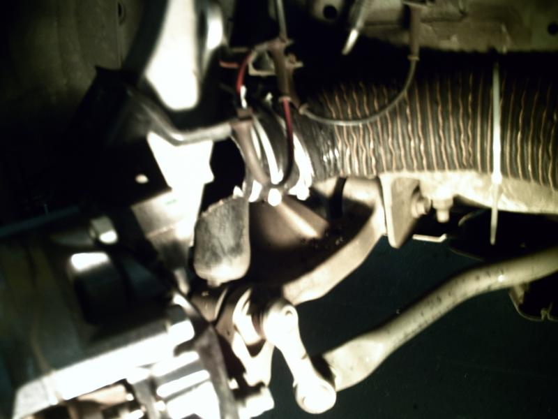
A couple of weeks after installing my new ducts I noticed that my ABS warning lot was coming on intermittently. After taking the wheels off I discovered what was going on.
The metal zip tie I used to secure the brake hose to the duct on the rotor was rubbing against the ABS line. It was starting to slowly cut through the line. Luckily, I noticed this before actually cutting through the insulation.
Although this picture is not the best angle, you can see how the line runs next the duct. I had to drill out the rivets on the passenger side duct (very easy to do) and move the duct about ½ inch away from the ABS sensor. It should be pretty obvious when you do the install. Just make sure that no part of the brake hose or clamp touches the ABS line or sensor.
Also, it would be a good time to remove the ABS sensor (10mm socket) and clean it off. Mine was covered in brake dust.


Next I cut the zip ties affixing the hose to the shock. I took this opportunity to trim the end of the old ducting (which was pretty beat up). I then used duct tape to connect the new section of brake ducting to the old section.
I then attached the new section of brake ducting to the new caliper duct.
Now you have to determine how long a section of brake ducting you will need. It has to be short enough that the ducting does not rub against the wheel at full lock in either direction.