Before proceeding with this install, I would advise reading the Racelogic TC manual just to get a good feel for what you will being doing in this DIY. I would also read through the entire DIY before starting as there are different tips and tricks you may want to use.
http://www.racelogic.co.uk/images/st...ual%20v3_2.pdf
Step 1 - Patch Harness
All wires discussed in Steps 1-3 in regards to the Racelogic unit are referring to connector A or the larger connector.
Unplug the negative terminal of your battery when any work is being done on the vehicle.
The patch harness comes in 2 pieces. There are two sets of connectors (F101/F102) that comes attached together. The smaller M107 connector comes by itself. There are a total of 8 wires (MT) or 9 wires (AT) that will need to be modified.
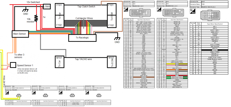
When modifying the harness, there will be two ends. One end that the car harness plugs into, and one end that plugs into the ECM. When working on the patch harness, its easiest to follow the nissan wiring diagram (attached on the image above) by looking at the end factory harness plugs into. You can tell which way to look at the plug by the diagram, but you can also tell which way by matching the larger wires on the end.
First make the decision on how you want to wire the Racelogic to the patch harness. There is the standard butt connectors, or soldering. Racelogic includes pins and harnesses if you would like the ability to unplug the unit from the harness. I chose to hardwire with butt connectors since I could remove the patch harness is needed.
Start with connector F102. This is the plug that goes to the middle connector of the ECM. Locate the 12 wires for the Racelogic. They will have 6 solid colors, and 6 matching colors with black stripes. You can also refer to the manual which has the color/pin chart. Locate wires 81, 82, 85, 86, 89, 90 on the patch harness. I recommend doing one wire at a time as not to get confused. I chose to cut close to the middle to make it easy to work with. The solid colors are the input, and the striped colors are the output. The easiest way to remember what you are doing is this:
ECM ---> Input RL (solid color)---> Output RL (striped color) ---> Harness (To injectors)
Cut wire 81. Attach a solid color (orange for example) to the wire coming from the ECM side of the harness. Attach the striped corresponding color (striped orange) to the side going to the car harness. Proceed to do the remaining 5 ECU wires with the remaining 10 Racelogic wires.
IMPORTANT* The color you chose to go to an injector does not matter (ie injector one could be any color from the RL harness) but you MUST make sure that you match the corresponding color/striped color to the same injector.
Once you have the 12 wires from the racelogic harness attached, move to harness M107. Locate wire 110 on the patch harness. Do not cut this wire! You are going to tap this wire with the white/black RPM wire from the racelogic. You will need to run a 10k resistor between the the 12v power wire for the racelogic and the white/black rpm wire. This is known as a pull up resistor.
This next part is for the AT guys only or if someone decides to go with a canbus model. Locate pins 113 and 114. Wire 113 is your CAN High, and 114 is your CAN Low. Tap these wires with the corresponding racelogic wires.
This part is for the MT with No Lift Shift only. If you get the no lift shift option, you will have an extra pin and a brown wire in your kit. You will need to attach the pin with a crimper and insert the pin into your racelogic harness at pin 20 (it's the only open spot). You will then locate pin 41 on connector F101, and tap this wire with the brown wire.
Your patch harness is now complete!
Step 2 - Wheelspeed Sensors (MT Guys only, AT guys goto Step 3)
I would recommend jacking the car at the front and removing the tires for easy access to your speed sensors. With that being said, if your impatient like I am you can reach your arm down the side and get to the sensor. You will have received 5 pieces to a wheel speed sensor kit. There will be 4 penny size sensors, and one larger one. You will need one of the penny sized sensors per wheel.
You will need the following wires for the install:
FL - Light Green
FR - Black
RR - Brown
RL - Orange or BG, depending on coupe or roadster. Mine was orange even though I have a coupe...
Start with the front left. The sensors will all have the same wire colors, red, brown, and orange. Cut the Light Green wire. Attach the red wire to the side coming from the sensor. Attach the brown wire to the side going to the harness. The orange wire will go to the main sensor. You will need enough wire to run from the sensor to the cabin. I chose to run both my fronts to the passenger side well grommet as that's where I put my Racelogic brain. Wrap the sensor and wiring and secure it off to the side. Rinse and repeat for the FL side.
IMPORTANT* You can do one of two things to make your life easier while programming the racelogic.
1) Keep track of which wire comes from which sensor
2) Run different color wires for each sensor to the main sensor
3) Keep your car jacked with all 4 tires off the ground.
The rears are significantly easier. Remove the spare tire. You will see a harness running at the top of the spare tire well. There are 4 wires inside, these are your wheel speed wires. Locate the corresponding wires and run to the cabin.
Attach the 4 wires coming from the speed sensors to the main unit. The main unit will have 10 wires.
4 input wires
4 output wires
power - attach these when you finish up the Racelogic harness
ground - attach these when you finish up the Racelogic harness. There is a ground at the end of the racelogic speedsensor wires, but it is kind of hard to attach to.
Attach the 4 wires from the sensors to the input wires. The 4 output wires will goto the racelogic unit. They are in a black wrap and are Red, blue, yellow, and green. If you used colored wires or kept track of each sensor wire, write down what output wire is going to what racelogic color (ie if you used orange wire for the FL and you attached the output to the Red RL wire, make sure you write this down). If your car is on jackstands you can skip this step if you wish.
Step 3 - Finishing the racelogic harness.
At this point you should have the following wires remaining from connector A:
Twisted pair ground - This should be straight forward
12v wire - This needs to be connected to a 12v switched source.
5 v wire - This is what you need the L7805 regulator or a 12v to 5 v converter. Once you have a 12v source for the racelogic selected, run two wires. One will goto the 12v input on the L7805. Hook up the racelogic to the 5v pin on the L7805, and hook up the ground on the L7805. If you are using a converter, you will need to follow the included instructions.
Step 4 - Adjuster/set-up
Depending on the adjusted selected, follow the racelogic instructions for connector B. Please note, that there is a difference between the digital and analog adjuster. You will receive a separate book for installing the adjuster from racelogic.
Plug the negative post back on the battery. If you wish you can fire the car up and confirm everything is working. With either the car on or in ACC mode, connect your laptop to the racelogic via the racelogic software.
This will be a very simple explanation of what you need to do. If you wish to play with different defaults you may do so.
Configuration Screen: Change number of cylinders to 6
Launch Control: You can change your launch control RPM in this screen, or with the digital adjuster if purchased.
Slip Control: You can adjust your cuts in this screen if you wish
Wheels: There are a few things to do in this screen. First is wheel diameter. There is a calculator programmed, click the tire to access it. Enter your tire specs for the proper calculation. Leave the pulses at 40.
Second is the tire channels. If you wrote down the colors or input wires, you will change each channel to the corresponding color. If you did not wire the colors, run a graph and check to see which tire is on what channel. Change the channel as needed. If your running the CANBUS model, this should not relate to you.
Rev Limits are for those with the no lift shift. Set the hard cut for your desired rev limit and set the soft cut 500-1000rpm under this (this will be personal preference, play with it). The no lift shift only works in this range. If you have a certain powerband you are trying to achieve (ie shifting before redline) set you hard cut to your desired rev limit. Keep in mind that the car will not rev past the hard cut.
The rest is straight forward. There is a turn radius config you can run, just follow the manual.
Thats it, have fun!
Completed Patch Harness (The note stickers are for other items i decided to tap at the same time, boost controller, knock light, ect...)

The connectors are color coded so you cannot mess them up. You can see above that the patch harness matches the colors.

Rear wheelspeed harness in the spare tire well

Front wheelspeed harness

Ground on the blower motor

Glove box removed. I left my unit behind the foam bar that is there against the firewall. You can see all the wiring coming in from the grommet

Grommet I ran all my front wiring through

Tapping the rear speed sensors

Tidy up rear sensors. You can see how small they are
